|
|
Post by mulmany on Jan 11, 2015 21:17:34 GMT -6
Ok, so you guys may have seen my U76 thead, and now I am looking to rectify the ground problem.
Can anyone direct me to an actual schematic or wiring diagram? I want to see how the common and both grounds are tied together.
I may be able to salvage both of these racks. Well, it would let me sleep at night! (The things we worry about)
|
|
|
|
Post by svart on Jan 11, 2015 21:59:07 GMT -6
I don't know about the API racks, but my DIY 500 rack just has all grounds going to a single ground.
|
|
|
|
Post by mulmany on Jan 11, 2015 22:35:10 GMT -6
I don't know about the API racks, but my DIY 500 rack just has all grounds going to a single ground. Audio, Chassis, and Power? |
|
|
|
Post by svart on Jan 11, 2015 22:44:38 GMT -6
I don't know about the API racks, but my DIY 500 rack just has all grounds going to a single ground. Audio, Chassis, and Power? Yup. |
|
|
|
Post by horvitz on Jan 12, 2015 5:07:54 GMT -6
I recently ran into an older BAE rack that had pin 5 (audio gnd) floating. Had to tie 5 to 13 on the PCB to get things working.
|
|
|
|
Post by mulmany on Jan 12, 2015 7:26:56 GMT -6
I recently ran into an older BAE rack that had pin 5 (audio gnd) floating. Had to tie 5 to 13 on the PCB to get things working. This OSA rack has pin 1 and pin 5 floating. I guess I just need to figure out an easy way to tie them all together. |
|
|
|
Post by mulmany on Jan 13, 2015 23:11:41 GMT -6
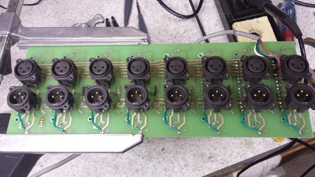
If you have a OSA rack you will need to jump pin 1 to the XLR pin 1. There is already a solder point for the XLR pin 1, so it just takes an 1.5" wire jumper. Now all the grounds will tie together when a module is in the slot. Also the Link jumper on this rack was facing the XLR's on the other side of backplane, there was no way to enable linking unless you took the whole rack apart. Silly!  |
|