|
|
Post by mulmany on Jan 9, 2015 19:14:59 GMT -6
I Just completed the build. I know some of you have built this unit. Getting some odd readings for the voltages. I am getting +10v where I should be reading +30v and -30v where I should be reading -10v. It is very odd. Build Docs , Schematic if anyone cares to look. Thanks |
|
|
|
Post by jeromemason on Jan 9, 2015 19:39:19 GMT -6
Is everything around and the lambda right? That's where I would start. I've got two of them to build soon myself. I never had any issues with my previous one though, fired up pretty much perfect.
|
|
|
|
Post by mulmany on Jan 9, 2015 20:55:27 GMT -6
Is everything around and the lambda right? That's where I would start. I've got two of them to build soon myself. I never had any issues with my previous one though, fired up pretty much perfect. I need to actually pull the board and go over in really well. It's a little funny that the voltages look like they are just swapped in polarity, the -10 is not even created on the converter board. |
|
|
|
Post by tonycamphd on Jan 9, 2015 21:01:52 GMT -6
Is everything around and the lambda right? That's where I would start. I've got two of them to build soon myself. I never had any issues with my previous one though, fired up pretty much perfect. I need to actually pull the board and go over in really well. It's a little funny that the voltages look like they are just swapped in polarity, the -10 is not even created on the converter board. pictures please P |
|
|
|
Post by jeromemason on Jan 9, 2015 23:56:07 GMT -6
Is everything around and the lambda right? That's where I would start. I've got two of them to build soon myself. I never had any issues with my previous one though, fired up pretty much perfect. I need to actually pull the board and go over in really well. It's a little funny that the voltages look like they are just swapped in polarity, the -10 is not even created on the converter board. Yeah, I think you've got something crossed, good news is there was no smoke and you actually saw voltages! So, you should be able to trace it down and I'm sure it's a simple fix. Pictures would be great, I remember that build pretty well. |
|
|
|
Post by svart on Jan 9, 2015 23:59:47 GMT -6
You've got your 10V zener backwards I'd bet.
The ground is floating due to the switcher isolation, so a backwards 10V zener would limit your 30V to 10V and wouldn't limit your -30V up to 10V.
Pretty sure that's it.
|
|
|
|
Post by unit7 on Jan 10, 2015 1:52:01 GMT -6
mulmany Just a general tip when you need help w DoN's kits. He doesn't seem to care about replying at GDIY (or haven't got the thread subscription setup properly) but I've found him very helpful via email. And he knows his kits very well!
|
|
|
|
Post by mulmany on Jan 10, 2015 10:12:52 GMT -6
Thanks Boys, I pulled the DC/DC board and checked and checked my 10v Zener orientation all was as spec'ed. I am emailing Dave, then going to do a resistor check. I will let you know what I find.   |
|
|
|
Post by svart on Jan 10, 2015 10:24:10 GMT -6
Hmm. I would have bet money on that zener. It's just too suspect that your difference is exactly 20V, which is what the zener would waste during regulation.
|
|
|
|
Post by mulmany on Jan 10, 2015 19:55:17 GMT -6
Yeah I was hoping... looks like it is a ground issue, all the grounds are not reading continuity. I am not quite there with reading how they all tie together. Pin 1/Pin 5/Pin 13.
|
|
|
|
Post by mulmany on Jan 11, 2015 16:16:52 GMT -6
Ok... well this was a simple fix.
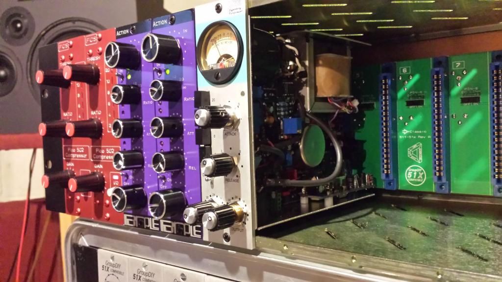
Put the unit in the 51x rack from CAPI!
So my old rack has a ground issue which is no surprise since I have had odd random issues with modules installed in it.
I thought it was because the chassis ground was broke... fixed it. Problem was still there. I guess I need to trouble shoot and fix my rack now.
|
|
|
|
Post by mulmany on Jan 11, 2015 19:07:58 GMT -6
Its alive! Calibration complete. Sounds Great! No issues at all with the build, it was all the rack. Thought I was going crazy!   |
|