|
|
Post by indiehouse on Jan 15, 2023 14:18:09 GMT -6
I have a Hakko 936 soldering station. I was working on something the other day, and my 6 year old daughter came down to the workshop. She was very curious and I loved answering all of her questions! As she was talking, and I was working, she started to cut through my soldering iron connector cable. obviously, this caused my soldering iron to quit working. I dug out an old Radio Shack iron and tried to repair the cable, but it didn't work, and I'm not sure why. I have continuity between all of the splice points where the cable was cut to all the pins. The white and black wires appear to be shorted together (continuity between them), but I can see no reason why. I assume that's intentional, because isn't that how the heat is generated? I started to wonder if she had shorted out something else when some of the cut wires all made contact with the wire cutters when she was cutting the cable. I cracked open the unit, but I'm not sure what to look for. The fuse is soldered in, and it appears in tact. There appears to be a damaged trace on the circuit board where the soldering iron plugs into. Not sure if that was intentional or not. Long term solution is to just buy another iron. But I want to make sure nothing else is toasted. I can't see why my splice job wouldn't get this working again. I need help! svart EmRR  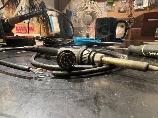 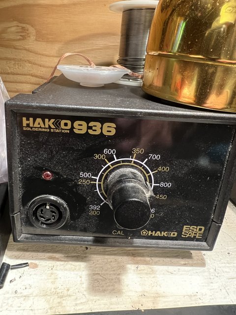  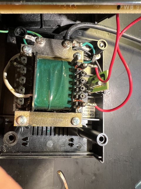 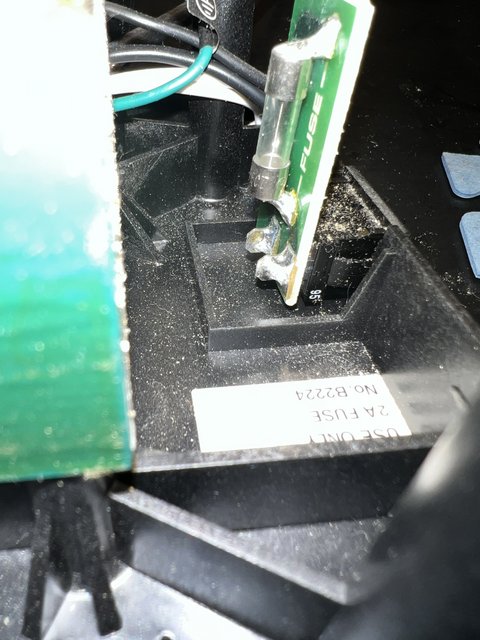  |
|
|
|
Post by svart on Jan 15, 2023 16:56:38 GMT -6
Got any pics of the top of the controller board?
|
|
|
|
Post by EmRR on Jan 15, 2023 17:53:59 GMT -6
I don’t know those.
|
|
|
|
Post by miadaudio on Jan 15, 2023 18:50:15 GMT -6
i'm not svart or EmRR and I'm not familiar with this station but here's the schematic. if I were you I would start by checking if all the voltages are correct (as long as you feel confident with measuring while the station being powered on of course!) BTW, do you get any continuity between the two middle pins? On the link above it doesn't seem to be any lifted trace like in your station (although I doubt that this is the problem) |
|
|
|
Post by indiehouse on Jan 16, 2023 14:10:09 GMT -6
Got any pics of the top of the controller board? Not easily. Looks like the whole board is only secured to the front panel via the input socket. Meaning, the soldering iron connector socket is fitted to the front panel first (snaps in place, only able to pull out from the front), and then the board is soldered to that. I’d have to desolder that part. I don’t see any fried components, from what I can tell. |
|
|
|
Post by indiehouse on Jan 16, 2023 14:22:58 GMT -6
i'm not svart or EmRR and I'm not familiar with this station but here's the schematic. if I were you I would start by checking if all the voltages are correct (as long as you feel confident with measuring while the station being powered on of course!) BTW, do you get any continuity between the two middle pins? On the link above it doesn't seem to be any lifted trace like in your station (although I doubt that this is the problem) Thanks for the help! I only get continuity from these two pins: 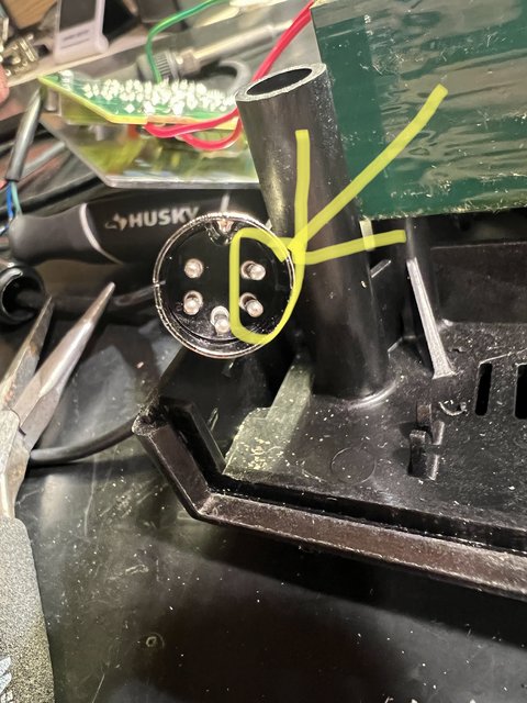 Interestingly, I don’t get continuity between the same connector solder points on the board. Probably because of the heat generated by the short. I will try to read the schematic. I wish I was better at that. |
|
|
|
Post by indiehouse on Jan 16, 2023 14:56:10 GMT -6
Well, I’m getting about 12VAC to the connector pins. I assume that’s correct.
|
|
|
|
Post by indiehouse on Jan 16, 2023 15:17:17 GMT -6
I’m getting 12VAC all the way up into the element. Interesting, blue and red wires have continuity as well. 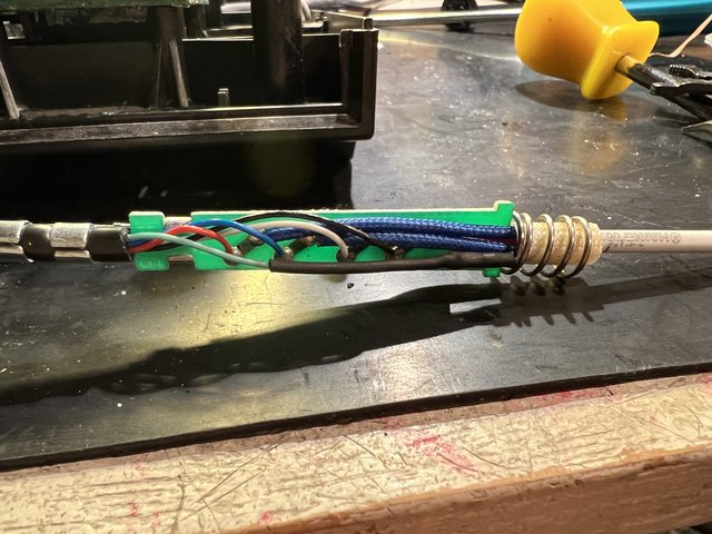 |
|
|
|
Post by svart on Jan 16, 2023 15:30:24 GMT -6
Well, I’m getting about 12VAC to the connector pins. I assume that’s correct. At which pins? The heater pins are fed by a triac. Triacs are like gated diodes. You'd see a partial 24VAC waveform between those pins with varying phase angle depending on the power required to heat until the thermocouple trigger point is met. The triac controller is like a timer that will turn the triac on during parts of the AC cycle. My bet is that the triac and/or the LM324 are dead. They should both be easily replaceable. Looks like the AC05D triac is EOL though. I'd avoid the Ebay chinese sourced ones at all costs. Closest I could find is: www.digikey.com/en/products/detail/ween-semiconductors/BTA206X-800ET-127/2779854 |
|
|
|
Post by miadaudio on Jan 17, 2023 4:08:36 GMT -6
I’m getting 12VAC all the way up into the element. Interesting, blue and red wires have continuity as well.  Unfortunately it is difficult to know what colours correspond to the pins since the schematic has no mention of the wire colours. BTW, you can test your triad by using your DMM but you'll have to desolder it. When you measure continuity, do you read the actual resistance value or you count only on hearing the beep sound? Most multimeters will beep even if there is a reasonable amount of resistance. The beeper is fine for speed but you should measure the actual resistance instead. Could you measure again the pins resistance (on the cable, not on the unit itself)? You should be getting very low resistance between the heater pins and a few tens of Ohms between the sensor pins. Also, do you have continuity (i.e anything between 0.1Ω to 2Ω) between the tip and Pin 3? |
|
|
|
Post by indiehouse on Jan 17, 2023 11:16:00 GMT -6
|
|
|
|
Post by svart on Jan 17, 2023 15:09:55 GMT -6
It's hard to say with Ebay. I've had luck with general logic, but specialty type stuff has turned out to be fakes. Something like this might still have NOS suppliers around but I bought some transistors from a US ebay distributor and they turned out to be fakes as well and had a hell of a time getting the seller to agree to a refund. So when you use your DMM in resistance mode, the DMM supplies a current through a resistor and measures the voltage drop. When testing a triac or SCR, it would supply a current to the gate and either of the other leads compared to the other which will turn it on in one of the operation quadrants. A triac or SCR are different from a FET or BJT where the gate needs to see current on both the gate and either terminal to do something at all. Anyway, I'd also replace the LM324 as a precaution. |
|
|
|
Post by indiehouse on Jan 19, 2023 9:55:33 GMT -6
Funny, Hakko responded and told me that my cable repair splices should have been heat shrinked, and by not doing so caused a short in the PCB board, with the recommended fix being to replace the entire PCB board, which is discontinued and out of stock, so they recommended buying another soldering station. Then I replied that I believe the damaged component is the AC05D, and I needed a recommended replacement since this part is discontinued. They replied that they actually have some of those in stock! They also have a replacement cable, it's like $40. Expensive. Anyways, they then asked if I was planning to bridge the pad/trace. I wasn't sure what they were referring to. I assume it was the photo of the damaged trace I sent. Do you think this looks like damage from a short? Or intentional, like someone cut it? Wouldn't there be charring or burn marks if it was shorted and caused the trace to what, essentially melt? This looks super clean to me. I suppose I need to know if this was intentional or not, as that would affect the repair. I can jumper that pretty easy with a wire. 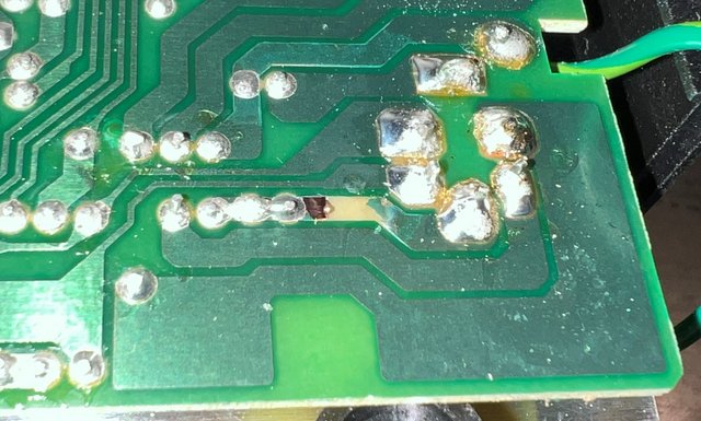 |
|
|
|
Post by svart on Jan 19, 2023 10:01:22 GMT -6
Funny, Hakko responded and told me that my cable repair splices should have been heat shrinked, and by not doing so caused a short in the PCB board, with the recommended fix being to replace the entire PCB board, which is discontinued and out of stock, so they recommended buying another soldering station. Then I replied that I believe the damaged component is the AC05D, and I needed a recommended replacement since this part is discontinued. They replied that they actually have some of those in stock! They also have a replacement cable, it's like $40. Expensive. Anyways, they then asked if I was planning to bridge the pad/trace. I wasn't sure what they were referring to. I assume it was the photo of the damaged trace I sent. Do you think this looks like damage from a short? Or intentional, like someone cut it? Wouldn't there be charring or burn marks if it was shorted and caused the trace to what, essentially melt? This looks super clean to me. I suppose I need to know if this was intentional or not, as that would affect the repair. I can jumper that pretty easy with a wire.  Damn. Completely missed that in the pics the first time. Traces can burn like that if there's enough current. What happens is that the copper will heat and pull from the fiberglass as it expands and then it'll quickly disintegrate like a fuse which won't leave burn marks. It's possible it was already coming loose from heating/cooling cycles over the years too. |
|
|
|
Post by miadaudio on Jan 19, 2023 10:21:58 GMT -6
It can happen yes. Try to bridge it. In the schematic it is connected to the top pin through a 1 MOhm resistor and to the chassis. Better use a thick wire.
|
|