u87 Removing Pad Reistors & Changing Transformer Load
Apr 21, 2020 0:09:25 GMT -6
EmRR and woofhead like this
Post by Bender on Apr 21, 2020 0:09:25 GMT -6
Doing some research and reading about how gotham audio added a couple of resistors to lower the volume, in addition to wiring the transformer load to 50 ohms vs the standard 200ohms found in europe. Basically changing these two things increases the S/N ratio and makes it 6dbish louder. I feel it all appears pretty easy and straightfoward but wanted to confirm that it's exactly as it seems before soldering in an expensive vintage microphone by confirming with some more savy DIY techies since there are no currently uploaded pictures to confirm the bridges are where I think they are.... I get a little confused and bolded out where I'm at.
As quoted from Klaus here's the background/ info on how to do it
---------------------------------------------------
How to remove the audio pads in the U87i and/or change the output transformer from 50 Ohms to 200 Ohms.
Most U87i microphones sold in the Americas until 1990, and some other Neumann FET microphones like all KM 8x-series and the FET 47 all were delivered with a reduced output, compared to the same models for European delivery. The output reduction was accomplished by adding a resistive pad in line with the output, and/or by strapping the output transformer’s two secondary coils in parallel, instead of in series. You may find both of these output attenuations in your mic or just one.
Microphones equipped with the Gotham pads are easily identified.
Look for a colored dot next to the serial number, which is embossed next to the XLR connector: if you find a red dot (through ca. 1978) or a light blue dot (from ca. 1978 to 1989) mics left the factory with lower output. If you see just a blank brass indentation without color fill, the mic has full European output.
The lowered output settings which were mandated for U.S.import by the then importer Gotham, New York, rob these FET mics of some of their aural beauty, and force higher gain settings from the mic preamp, resulting in a lower signal-to-noise ratio.
How to remove the U87 output pad resistors
-Remove the housing tube by unscrewing the mic’s bottom bell
-Unscrew two tiny slot screws which fasten the battery lid to the two long frame bars
-Tilt the battery lid upwards
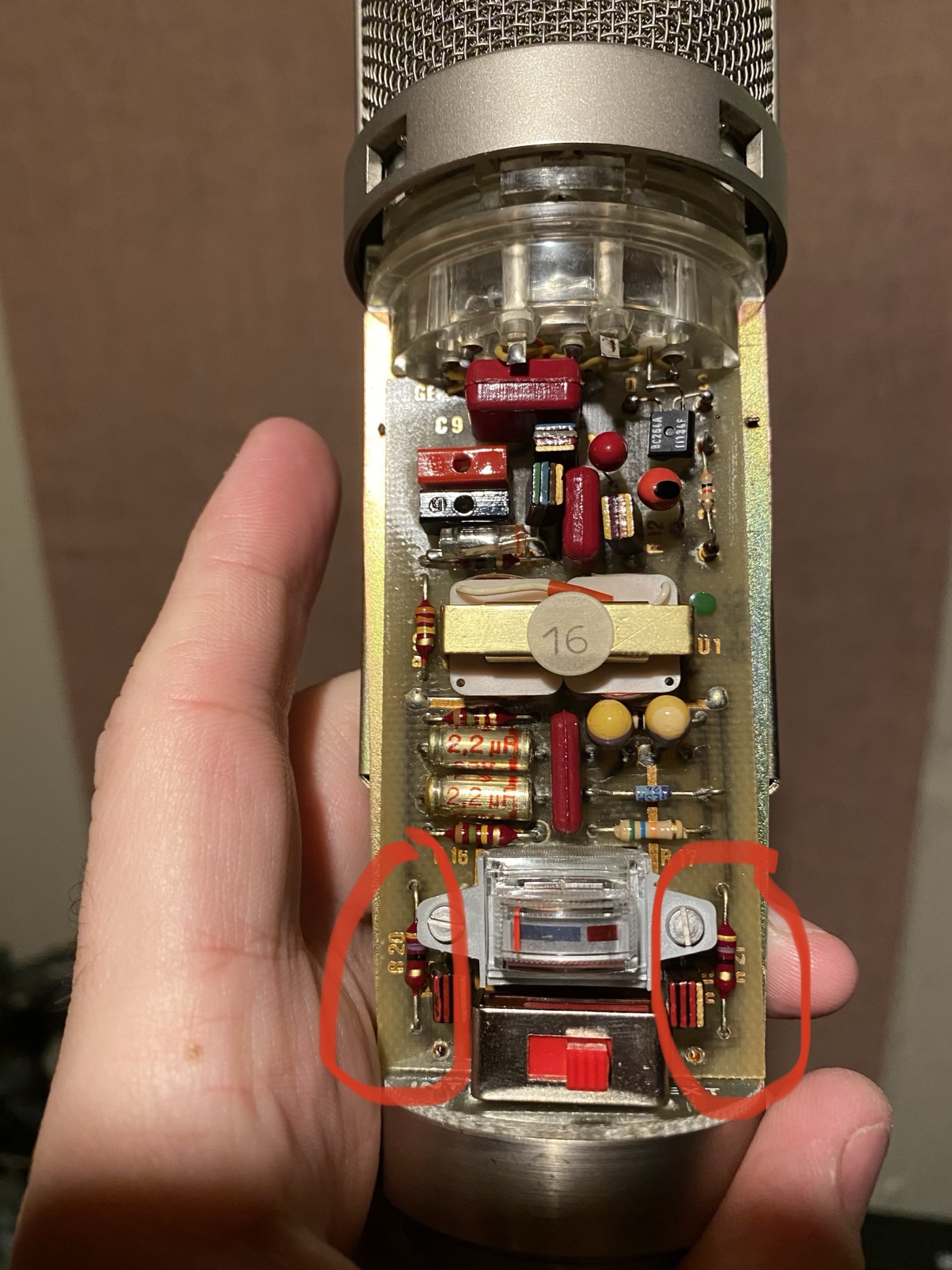
-Look on the component side of the circuit board (opposite side of the battery lid) for two 47 Ohm resistors (color markings yellow, purple, black and gold), which are mounted on each side of the battery switch, close to the round metal piece which houses the XLR connector. Markings on the circuit board further identify these resistors: “R19” and “R20”.
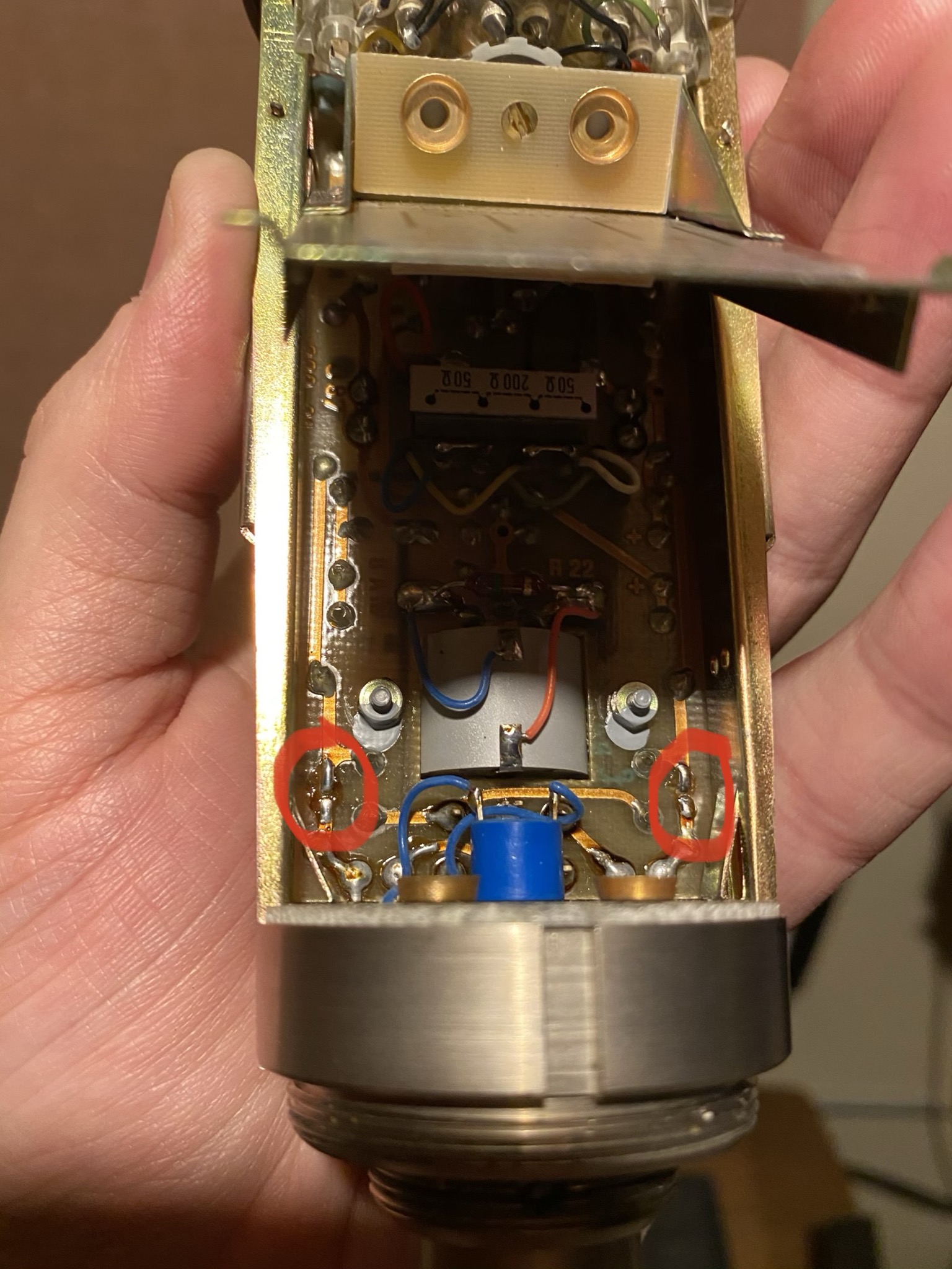
-Now, rotate the mic 180 degrees and look at the solder side of the circuit board: you will find a solder spot connecting to each leg of the 47 Ohm resistors. In order to bypass each resistor, all you need to do is to bridge the two solder spots, either with a blob of melted solder, or with a piece of wire soldered to the two points.
Now you have bridged the two resistors and they are no longer active.
This procedure will increase the mic’s output between 4 and 6dB.
Note: mics which were already converted have bare bridging wires instead of the resistors, or the resistors are already bridged with solder blobs at the factory.
Changing the output transformer’s impedance from 50 to 200 Ohms
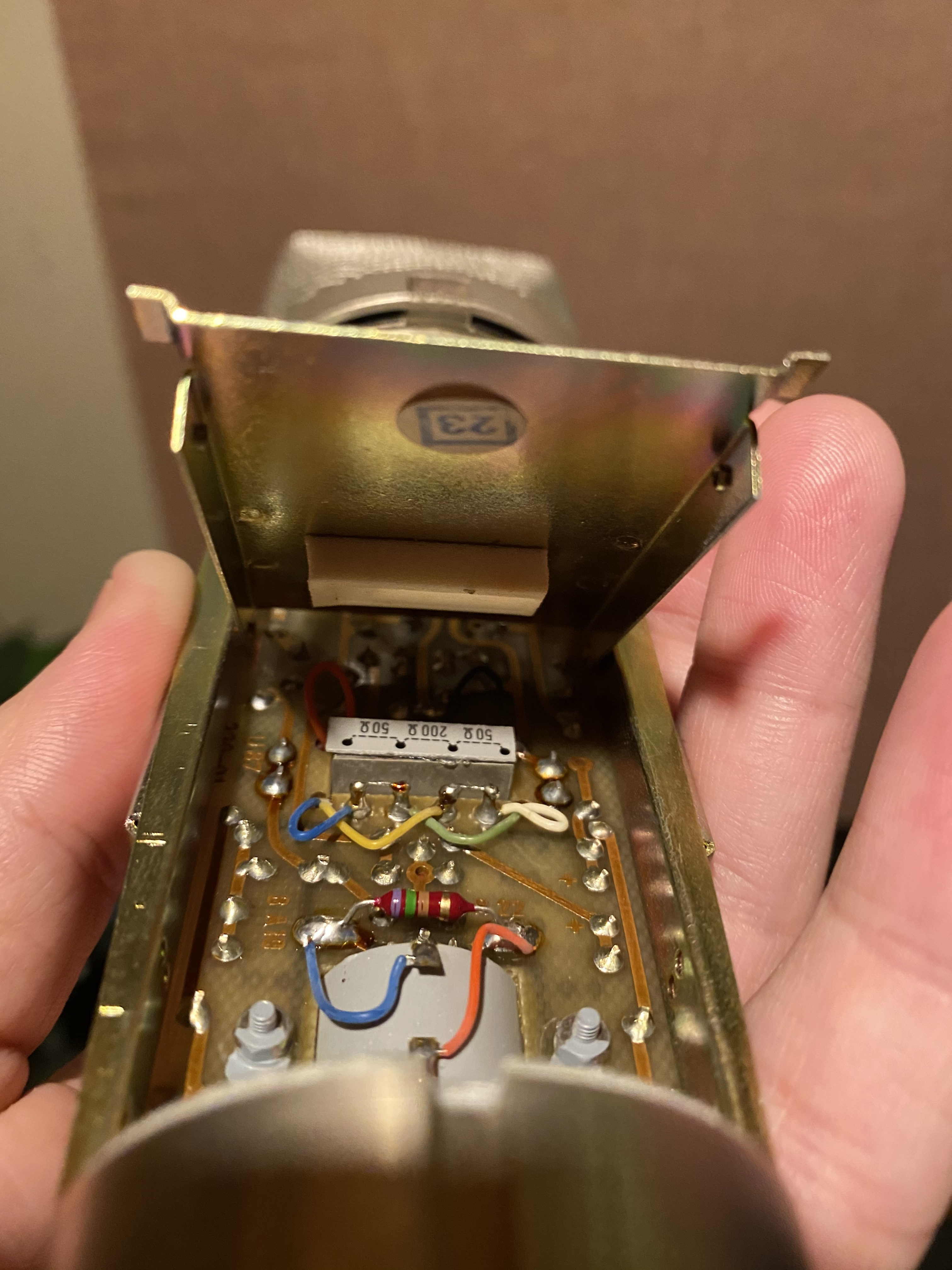
The U87’s transformer is in the center of the circuit board: you will notice two copper coils with white plastic frames. With the battery lid up, look at the back side of the transformer: below its rectangular metal core you will find four mounting posts. A colored wire is soldered to each of these posts. Orienting the mic with the head up and the connector at the bottom, the wires are, from left to right: blue, green, yellow, white.
The transformer is set up for 50 Ohms, when you see two wire jumpers: the blue and the green wires are bridged, so are the yellow and white wires.
-For 200 Ohms, remove both jumpers, and reinstall one of them to bridge the two middle posts only: green and yellow.
This procedure will increase the mic’s output about 6dB.
----------------------------------------------------------------
So my 70's 87 has a red dot on the bottom and opening it up it appears to be loaded in 50ohm configuration. I've added some pics with the resistors circled in red on the bottom corners.

Flipping it around to other side and see where the two points are, I'm a little confused, do I solder the two points I've circled? It's one leg of the resistor to something else- but it certainly looks like a blob of solder will do the trick.


As Far as the wiring of the transformer goes, I just remove the two bridges connecting blue and green / yellow & white, and replace it with one in the middle connecting Green & yellow Right?

Mic sounds great, just after reading that I see no reason why add some volume since this certainly aint going into a vintage tube console designed for ribbons etc...


