|
|
Post by matt@IAA on Jul 26, 2018 21:03:30 GMT -6
A friend of mine asked me to put together a 4 channel preamp for a 1RU configuration. Its a four channel 312 board, each with pad, polarity, mute, and phantom power switch. It also has a place for a 600 ohm T-pad attenuation, which you can get from CAPI. I've set it up so you can bypass it with a solder jumper if you're not going to install them (or you could use the pads for a load resistor). You could use whatever input and output transformers you want, as well as whatever DOA in 2520 footprint. I also included an onboard PSU.  The minimum buy from the PCB house is 5, but I can order more if people are interested. If you want one, let me know. |
|
|
|
Post by matt@IAA on Jul 27, 2018 8:09:19 GMT -6
In the same vein, I’m going to be ordering 4 input and 4 output transformers from cinemag. At 10 you get a discount. If anyone wants a Cinemag CM3301 output or CM-3123PC input we can group buy.
|
|
|
|
Post by svart on Jul 27, 2018 9:51:59 GMT -6
Neat stuff.
In lieu of heatsinks, you could mount the regulators on the edge and bend them to mount to the chassis. Heatsinks don't work too well in enclosed chassis. They end up working more like heating elements in ovens and heatsoaking the whole airspace. At least chassis mounting allows a heat-plate effect to wick as much heat as possible to the large surface area of the metalwork and rack.
Also, is there a reason to order cinemags over Jeff's transformers? His are pretty spot on for replicas of the original API transformers.
|
|
|
|
Post by matt@IAA on Jul 27, 2018 14:56:59 GMT -6
I noticed you did that on the SSL one. On this one, it isn't going into a 19" rack unit for my friend, he wants it in a different format box. But, you could always mount them under the pcb and laid flat. I did check the heat calc on the sink though. For a 317/337 Rjc is 3 C/W, with thermalsil Rcs is 1.5 C/W (really good article here: www.onsemi.jp/PowerSolutions/document/AN1040-D.PDF)V in is 28, V out is 16 for an op amp voltage of 15, so delta V = 13V. Q is 60 mA per op amp * 4 op amps * 13V = 3.12 W Tj max is 125C. So you can either pick ambient temperature and Tj max and solve for your required Rsa (sink to ambient) or pick an Rsa and ambient and find your Tj. You get the idea. Rsa = (Tj max - T amb) / Q - Rjc - Rcs For an arbitrarily selected Tj max = 100 C and T ambient = 40 C, the Rsa comes out to 14.7 C/W max. Solving for Tj, Tj = (Rsa+Rjc+Rcs)*Q+Tamb With a 13.7 C/W heatsink, and 50 C ambient, the TJ comes out to ~106C. This jives with the passive heat sink surface temp rise vs heat dissipation curve given in the datasheet for the heatsink (3.5W = ~40C above ambient). All that is for all four op amps sucking down their rated amperage, of course. No reason for not CAPI, my friend picked the transformers based on whatever criteria he used. We talked about CAPI, Jensen, and Cinemag. |
|
|
|
Post by svart on Jul 27, 2018 16:00:59 GMT -6
Just reading on my phone as I head home, I'll look more thoroughly later..
You should add 25% overhead to all expected current values to account for parasitic losses, part tolerances, etc.
All junctioned semiconductors have positive TC, so they become less efficient with temp increase, and therefore increase self-heating through resistive losses..
Resistors have this effect to some degree and are generally rated for TC/ppm.
For those watching at home, the hotter parts get, the more heat they put out! This can lead to thermal runaway..
Some believe that most destructive deconstruction (aka parts blowing up) are not necessarily from over-current/voltage, but from thermal runaway due to the over-power situation and not being able to handle the heat. Some credence is lent to this when studying the ability to vastly over-power a semiconductor when they are actively aggressively cooled, like using liquid nitrogen on CPUs to gain huge overclocking numbers when running then at much higher voltages than designed for.
|
|
|
|
Post by matt@IAA on Jul 27, 2018 17:27:46 GMT -6
The current at rated output on the 2520 datasheet is 60 mA doing +20 dBu into a 75 ohm load. It drops all the way to 18 mA for 600 ohms, and quiescent current is 15 mA. I will be absolutely shocked if anyone does all four channels sustained st that even one time with one of these boxes hahah.
|
|
|
|
Post by matt@IAA on Jul 28, 2018 8:46:05 GMT -6
Well, the 10 I ordered are all spoken for but one. That went faster than I expected.
|
|
|
|
Post by svart on Jul 30, 2018 11:51:20 GMT -6
I noticed you did that on the SSL one. On this one, it isn't going into a 19" rack unit for my friend, he wants it in a different format box. But, you could always mount them under the pcb and laid flat. I did check the heat calc on the sink though. For a 317/337 Rjc is 3 C/W, with thermalsil Rcs is 1.5 C/W (really good article here: www.onsemi.jp/PowerSolutions/document/AN1040-D.PDF)V in is 28, V out is 16 for an op amp voltage of 15, so delta V = 13V. Q is 60 mA per op amp * 4 op amps * 13V = 3.12 W Tj max is 125C. So you can either pick ambient temperature and Tj max and solve for your required Rsa (sink to ambient) or pick an Rsa and ambient and find your Tj. You get the idea. Rsa = (Tj max - T amb) / Q - Rjc - Rcs For an arbitrarily selected Tj max = 100 C and T ambient = 40 C, the Rsa comes out to 14.7 C/W max. Solving for Tj, Tj = (Rsa+Rjc+Rcs)*Q+Tamb With a 13.7 C/W heatsink, and 50 C ambient, the TJ comes out to ~106C. This jives with the passive heat sink surface temp rise vs heat dissipation curve given in the datasheet for the heatsink (3.5W = ~40C above ambient). All that is for all four op amps sucking down their rated amperage, of course. No reason for not CAPI, my friend picked the transformers based on whatever criteria he used. We talked about CAPI, Jensen, and Cinemag. Reading through this, and the document you supplied, which I think I've actually seen before when doing IGBT/MOSFET power designs a decade ago. Your math seems correct for the junction temp/heatsink rise above ambient, but I don't see where you've addressed my original concern, which is lack of airflow in an enclosed chassis. Heatsinks are good to move heat into the air, but what happens when the air temps rise to the point of being saturated? Most heatsink datasheets I've seen assume airflow/airmass sufficient to drop the surface temp back to ambient(in an effort to rate heatsink efficiency), but in an enclosed chassis without forced ventilation, or otherwise open enough to allow convection, your localized ambient temp will eventually rise to meet the heatsink temperatures minus some percentage that the chassis absorbs from the internal airmass exposure. I can't say I've ever seen one that gave data on fully enclosed systems. I've seen it bite people before. We had a guy build some power amps that put out something like 5W in a tiny little case with no active or passive cooling. The PCB had little thermal connection to the chassis as well.. And they wondered why in the field these things would ultimately stop working since they would measure ambient temps inside the chassis and they'd be relatively cool and well under any failure threshold.. But it turned out that the user would leave the units on all the time, and under loading would rise well above safe junction temp for short periods of time. I ultimately had to "fix" the problem, and since it had to be weather-tight, there could not be any forced-air cooling. I increased the PCB from two layers to 4 (1 signal/power and 3 ground), and via stitched all the extra ground layers together with hundreds of vias and then increased the number of screw connections to the chassis to wick the heat away. Externally I added a heatsink to the chassis and was able to get Tj down to something reasonable for use. Now all of our designs have to have industrial/mechanical engineer approval for heat/cold. I never underestimate the ability for electronics to overheat since then! But I do understand that this is very unlikely in such a low current application, with an inherently large PCB/chassis for the currents involved. I'm just musing concerns I suppose. |
|
|
|
Post by matt@IAA on Jul 30, 2018 13:35:53 GMT -6
I definitely appreciate the real world cold eye review! The heat sink datasheet chart has a line for passive cooling - natural convection, that is, not forced - as well as for forced. In this case I'm considering T ambient to be the internal temperature of the box, and no forced convection whatsoever. Without forced convection the heat sink WILL increase to 40 C above ambient if it is loaded with 3 watts, regardless of what those absolute temperatures are. It will continue doing this as the ambient temperature rises until the temperature cascade from ambient to heat sink to coupling to case to junction hits the junction max temperature and the poor lil IC cooks. I just arbitrarily picked a hot internal box temperature (40-50C), with the assumption that the case itself will be a fairly large heat sink and radiator to the outside world. But you've piqued my interest now...so...putting on my nerd hat.... When you do thermal analysis for something like this you look at it from a thermodynamic perspective, that is, ignoring transient conditions (which is heat transfer and is less fun). If we consider steady state, we can make a good assumption that the outside room is more or less an infinite heat reservoir of a fixed temperature - 1 ton of cooling in an AC unit is 3500 watts! A human being, for example, produces about 100 watts of heat load. In normal conditions you are not going to notice turning on even a 100 watt power supply, any more than you may notice a temperature change from a second person in the room with you. So the room is what it is, let's call it 25 C (~75 F). As you dump heat into the box, the air inside is going to start at that same 25, and within a short amount of time the heat sink is going to be 40 degrees above that to achieve the dissipation of 3 watts into the box. Of course, this heats the air inside the box. But as soon as that box air is hotter than the case itself, there is going to be convective heat transfer between the air and the case (never mind the radiation from the heat sink fins to the case). And likewise, as the case surface heats up it starts to warm the room by convection, but we've already made life simple to say that the room has infinite capacity, so it will be constant temperature of 25 C. Then you can draw the whole thing out, just like a voltage cascade through a bunch of resistors. There is a steady state that will be achieved in short order, where the Tj is the highest temperature, just like V supply, and the ambient 25 is your 0 ref. Current is constant through the whole cascade. So the equation is now exactly the same as before, except the sum of your resistances includes three more terms - RAB (resistance of air internal to box), RBB (conductivity within the box), and RBAA (resistance of box to ambient air). For simplicity, I would ignore the temperature gradient across the wall of the case (it is going to be fairly small) and just suggest that there's some convection happening on both sides in a combined lumped model, RBA. Natural convection is obnoxiously complicated but we can simplify it to this graph just like the one in the heat sink datasheet, and only count the lid of our box, say 9" deep by 15" wide for 1 RU, 135 sq inches or .087 sq. m. This is giving us h, the convective heat transfer coefficient, which is q= hAdT, where q is our heat load, A is the surface area, and dT is the temperature differential. Multiply the number on the left by the .087 and we have W/C - invert it to get resistance, C/W and now we can sum it with our other terms. 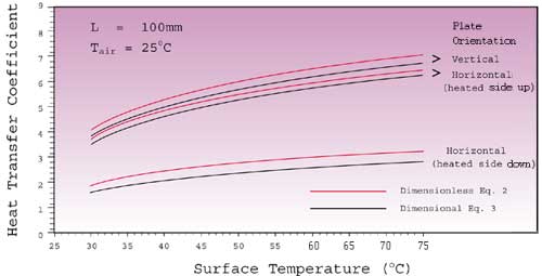 Earlier I said the inside of the box is 50, so that means the heat transfer coefficient h from the bottom line on the graph is ~2 W/(m^2*C), which gives us a thermal resistance RBA of 5.75 C/W. The line is pretty flat - the whole range from 30 to 75 only covers an h value of 1.6 to 2.8, or a resistance of 4.1 to 7.1 C/W. Our Tj then is [RSA + RJC + RCS + RBA]*Q + Tair = Tj Tj solves out to 94-103C across that range of resistances. In that same temperature cascade, you can rearrange the values to solve for the temperature at each point. For that solution, the temperature inside the box is 47C. If we raise the room temperature Tair to 40 C (ugh) the box will be 62 C, and your junction temperature is now getting pretty nasty, 119 C. This is all passive cooling, and doesn't count ventilation (the case will certainly be ventilated) or convection from the rest of the case (bottom, sides). Obviously the case will probably be rack mounted and it may be warmer around it...all models are wrong, but some are useful. I'm fairly satisfied, though, that in this case that there's more than enough passive cooling even considering that the air inside the box is heating up. |
|