|
|
Post by Johnkenn on Apr 13, 2017 14:33:20 GMT -6
So I've got my VP28 built, but I'm not getting any signal unless the output fade is on 8, 10 or 12. Once there, sound passes (albeit loudly lol) and the input knob seems to work fine. Switch the output to anything under 8 (5 o'clock) and nothing.
I would have thought cold solder, but I've re-flowed everything and really looked closely - nothing looks bad. Double checked and all my resistors are correct. Diodes the right direction. Anyone have any suggestions?
|
|
|
|
Post by indiehouse on Apr 13, 2017 14:40:56 GMT -6
So I've got my VP28 built, but I'm not getting any signal unless the output fade is on 8, 10 or 12. Once there, sound passes (albeit loudly lol) and the input knob seems to work fine. Switch the output to anything under 8 (5 o'clock) and nothing. I would have thought cold solder, but I've re-flowed everything and really looked closely - nothing looks bad. Double checked and all my resistors are correct. Diodes the right direction. Anyone have any suggestions? What op amps are you using? |
|
|
|
Post by Johnkenn on Apr 13, 2017 15:49:53 GMT -6
A 1731 and Red Dot...but I know they work, I pulled them out of another unit
|
|
|
|
Post by indiehouse on Apr 13, 2017 16:29:42 GMT -6
You able to post any photos (top/bottom)?
|
|
|
|
Post by Johnkenn on Apr 13, 2017 17:26:04 GMT -6
I'll try and get something up...Now I'm thinking it's NOT a cold solder joint, though...The Fader is acting like an ON/OFF switch. If I turn it to 8, then it passes sound. It doesn't get any louder when going higher. If you turn up the input (with the output at 8 or more), it gets louder as you turn it up like it should. I double checked all the resistors...hmmm.
Does anyone have one of the Rev B.1 versions with the green board? If so, could I trouble you for a pic? I just want to compare and see what I've done wrong.
|
|
|
|
Post by Johnkenn on Apr 13, 2017 17:35:46 GMT -6
I've GOT to have something in the wrong place. I guess my question is if this makes anybody go, "Oh, that's a cold solder..." or whatever. I always thought a cold solder would be more like it was cutting in and out...This sounds totally normal if I engage the pad and use the Input to drive the signal.
|
|
|
|
Post by indiehouse on Apr 13, 2017 18:33:56 GMT -6
I've GOT to have something in the wrong place. I guess my question is if this makes anybody go, "Oh, that's a cold solder..." or whatever. I always thought a cold solder would be more like it was cutting in and out...This sounds totally normal if I engage the pad and use the Input to drive the signal. Emailed you a photo. |
|
|
|
Post by mulmany on Apr 13, 2017 18:33:57 GMT -6
Sounds like a solder bridge.
|
|
|
|
Post by rowmat on Apr 13, 2017 18:41:28 GMT -6
Sounds like a solder bridge. Beat me to it! I would check the gain switch terminations for bridges. |
|
|
|
Post by kcatthedog on Apr 13, 2017 18:45:02 GMT -6
A solder bridge would electrically connect two parts that aren't supposed to be connected so screws up the circuit ?
|
|
|
|
Post by Johnkenn on Apr 13, 2017 19:13:21 GMT -6
Sounds like a solder bridge. Beat me to it! I would check the gain switch terminations for bridges. Speak English, Mick... (Jumping Jack Flash Reference)... Anyway, I wicked up the solder on the Fader gainswitch's and re-soldered...You're saying do the same on the Input Gain Switch? Even though it's not the issue at first blush...? |
|
|
|
Post by indiehouse on Apr 14, 2017 5:52:33 GMT -6
Beat me to it! I would check the gain switch terminations for bridges. Speak English, Mick... (Jumping Jack Flash Reference)... Anyway, I wicked up the solder on the Fader gainswitch's and re-soldered...You're saying do the same on the Input Gain Switch? Even though it's not the issue at first blush...? He's saying to check the solder points on the fader gainswitch to make sure that no two points are making contact. The spacing is tight, and it's easy to have solder flow from one point to another. Grab a magnifying glass. |
|
|
|
Post by Johnkenn on Apr 14, 2017 8:20:47 GMT -6
Thanks!
|
|
Deleted
Deleted Member
Posts: 0
|
Post by Deleted on Apr 15, 2017 13:39:42 GMT -6
John,
How goes the troubleshooting? I'm looking to build one of these at some point and wondering what could have caused this.
|
|
|
|
Post by Johnkenn on Apr 15, 2017 15:54:05 GMT -6
No answers
|
|
|
|
Post by Guitar on Apr 18, 2017 18:28:14 GMT -6
Did you get it working yet? Spotty soldering has plagued me in the past with CAPI builds. As well as a few other weird problems like flux getting on the PCB pins at the connector end.
|
|
|
|
Post by Johnkenn on Apr 18, 2017 22:56:49 GMT -6
Did you get it working yet? Spotty soldering has plagued me in the past with CAPI builds. As well as a few other weird problems like flux getting on the PCB pins at the connector end. Thanks man. No. Haven't figured it out yet. Pretty frustrating. I bought some Kester solder. Was using radio shack shit so who knows. Gonna try and touch up. |
|
|
|
Post by ChaseUTB on Apr 18, 2017 23:00:23 GMT -6
Did you get it working yet? Spotty soldering has plagued me in the past with CAPI builds. As well as a few other weird problems like flux getting on the PCB pins at the connector end. Thanks man. No. Haven't figured it out yet. Pretty frustrating. I bought some jester solder. Was using radio shack shit so who knows. Gonna try and touch up. You got this man 😎✅ |
|
Deleted
Deleted Member
Posts: 0
|
Post by Deleted on Apr 20, 2017 10:49:47 GMT -6
Have you been able to rule out if the output pot itself is the issue? Just spitballing here, but is there a way to test with a DMM if the output pot itself is functioning properly?
|
|
|
|
Post by Johnkenn on Apr 20, 2017 12:12:08 GMT -6
Well, I'm not really a smarty with the technical stuff. lol. But I do have a multimeter...anyone want to tell me how to check  ? |
|
|
|
Post by ChaseUTB on Apr 22, 2017 3:22:17 GMT -6
Well, I'm not really a smarty with the technical stuff. lol. But I do have a multimeter...anyone want to tell me how to check ? Continutiy? To see if it's a completed circuit? Idk I'm not the best with this stuff.. sorry if my answer is super noob and way off like Samsonite .... |
|
|
|
Post by jsteiger on Apr 22, 2017 13:39:34 GMT -6
This is a screenshot of the VP28 fader switch. The view is from the bottom of the PCB. You should have 0Ω between the green line connected points when at the respective settings. And of course you must check ever step in between but I did not label those. 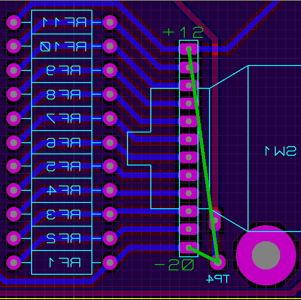 |
|
|
|
Post by Johnkenn on Apr 22, 2017 14:47:13 GMT -6
This is a screenshot of the VP28 fader switch. The view is from the bottom of the PCB. You should have 0Ω between the green line connected points when at the respective settings. And of course you must check ever step in between but I did not label those. Thanks, Jeff! Might try and tackle this tonight. |
|
|
|
Post by javamad on May 18, 2017 1:49:15 GMT -6
So, how does the story end? Were you able to get this working?
This is exactly the scenario that has me thinking that I should just pay for real API gear. I would be worried that I would mess up a build and have something cost a few hundred bucks but does not work.
Not to criticize ... but the capi-gear website is not exactly user/newbie friendly either. I would have expected some youtube videos of builds, etc ... maybe I missed them?
Anyway for the moment I will be staying away - due to doubts about my own ability to do a build, not the quality of a properly built unit which is vouched for on this and other forums.
|
|
|
|
Post by unit7 on May 18, 2017 2:07:14 GMT -6
So, how does the story end? Were you able to get this working? This is exactly the scenario that has me thinking that I should just pay for real API gear. I would be worried that I would mess up a build and have something cost a few hundred bucks but does not work. Not to criticize ... but the capi-gear website is not exactly user/newbie friendly either. I would have expected some youtube videos of builds, etc ... maybe I missed them? Anyway for the moment I will be staying away - due to doubts about my own ability to do a build, not the quality of a properly built unit which is vouched for on this and other forums. At the CAPI product pages there are links to support pages at a place called GDIY. |
|


 ?
?


